


Wireless power transfer via inductive coupling
Note:
Schematics and information about the circuit is now available at 4hv.org:
http://4hv.org/e107_plugins/forum/for...
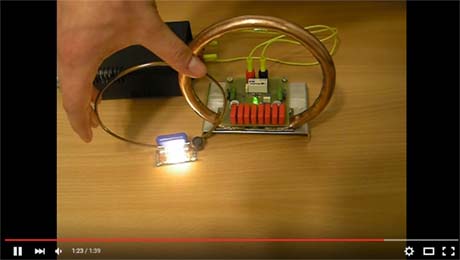
This is a small scale demonstration of wireless power transfer between two coupled parallel LC tuned circuits, each consisting of a copper conductor loop acting as an inductor and a capacitor. Both LC circuits are tuned to equal individual resonant frequencies. One of them is a part of a 1.5Mhz radio frequency oscillator powered by 12 volts DC, while another is loaded by a 24V 5W incandescent light bulb. Brought in proximity, copper loops share a small mutual inductance, essentially forming a transformer. In order to transmit significant amount of power through this transformer a very large amount of reactive power needs to circulate in it's primary, requiring use of a thick copper tube for the conductor, and a bank of eight 6.8nF capacitors in parallel.
Receiver coil's leakage inductance is in turn canceled out by another capacitor, allowing for the maximum power transfer to the load.
Experimenting with copper loop orientations, one can find positions of the receiver close to transmitter where no power is received, as total magnetic flux crossing through the receiver loop is zero. Hence this is a directional method of power transmission.
Due to small size of the apparatus very little power is actually radiated in far field, with losses being mainly ohmic heating. Hence this method is also sometimes known as non-radiative or near-field power transmission.