ทุกท่านอาจจะคิดว่าการวัดเป็นเรื่องที่ง่ายและอย่างแย่ที่สุดก็ไม่สามารถอ่านค่าได้ถูกต้อง
ทุกท่านอาจจะคิดว่าการวัดเป็นเรื่องที่ง่ายและอย่างแย่ที่สุดก็ไม่สามารถอ่านค่าได้ถูกต้อง แต่จริง ๆ แล้วผู้คนส่วนใหญ่กลับลืมไปว่าการวัดนั้นมีความเสี่ยงที่จะทำให้เครื่องมือราคานับหมื่นนับแสนเสียหายหรือบางครั้งการวัดอาจก่อให้เกิดประกายไฟซึ่งสามารถทำให้เกิดเพลิงไหม้ขึ้นได้
You'd think taking a measurement is a simple task and the worst thing that could really happen is that you may get erroneous readings, but what most people fail to realize is the potential of a hazardous situation that could essentially damage thousands of dollars worth of equipment or create an arc-flash hazard which could lead to either a fire or serious physical burns or potentially both.
เพื่อให้เข้าใจง่ายขึ้นให้ลองพิจารณาถึงการใช้มัลติมิเตอร์ทำการวัดค่าแรงดันไฟฟ้าระหว่างจุดต่าง ๆ ในวงจรแต่กลับปรับให้มัลติมิเตอร์ทำงานในรูปแบบการวัดกระแสไฟฟ้า ความต้านทานซึ่งต่ำมาก ๆ ในการวัดกระแสไฟฟ้าจะทำให้เกิดการลัดวงจรขึ้นซึ่งจะทำให้เกิดกระแสไฟกระชากซึ่งทำให้มัลติมิเตอร์เสียหายและผู้ใช้งานจะถูกไฟช๊อต แต่สิ่งเหล่านี้ไม่เกิดขึ้นเนื่องจากในมัลติมิเตอร์จะมีการใส่ฟิวส์ไว้เพื่อความปลอดภัยในการใช้งาน
To explain this simply, consider a case of Digital Multimeter (DMM) using which the user wants to measure Voltage in Voltmeter mode across a circuit but instead ends up connecting it as an Ammeter across the circuit. The minimal resistance of the Ammeter will create a short circuit condition and as a result there will be a current surge which could damage the DMM and cause an electric shock to the user but this does not happen and to avoid this possibility, the DMMs have a fuse which provides the requisite safety.
เช่นเดียวกัน ระบบวัดและบันทึกข้อมูลก็ควรจะมีคุณสมบัติด้านความปลอดภัยเหล่านี้ ซึ่งคุณสมบัติที่สำคัญที่สุดก็คือ ไอโซเลชั่น ในบทความนี้ เราจะมาทำความเข้าใจถึงระบบไอโซเลชั่นในรูปแบบต่าง ๆ และวิธีการเลือกระบบไอโซเลชั่นที่ให้กับการใช้งาน
Similarly, for any measurement system or data acquisition system it is critical to have some safety features, the most needed of them being the Isolation. In this article, the focus lies on understanding different types of isolation and ultimately choosing the measurement system with optimum isolation levels as needed for the application.
ไอโซเลชั่น
Isolation
ไอโซเลชั่น คือ การแยกจากกันทางกายภาพและทางไฟฟ้าขององค์ประกอบสองส่วนในอุปกรณ์ ไอโซเลชั่นช่วยป้องกันเครื่องมือวัด วงจรคอมพิวเตอร์ และผู้ใช้งาน นอกจากนี้ยังป้องกันการเกิดกราวนด์ลูป (ground loop) และปรับปรุงแรงดันไฟฟ้าร่วม (common-mode voltage) และกำจัดสัญญาณรบกวนในสภาวะแวดล้อมที่เต็มไปด้วยสัญญาณรบกวนทางไฟฟ้าจากเครื่องจักรและขดลวดเหนี่ยวนำ
Isolation is defined as the means of physically and electrically separating two parts of a device. It protects the measurement device, computer circuitry and human operators, breaks ground loops and improves common-mode voltage and noise rejection in electrically noisy environments containing machinery and inductive loads.
ลองพิจารณาถึงระบบวัดในการทดสอบเครื่องยนต์สันดาปภายใน ซึ่งมีแรงดันไฟฟ้าร่วมมากมายหลายจุดในเครื่องยนต์และยังมีโอกาสที่จะเกิดไฟกระชากสูง ยกตัวอย่างเช่น เราใช้เทอร์โมคัปเปิ้ลในการวัดอุณหภูมิกระบอกสูบซึ่งแรงดันไฟฟ้าที่อ่านได้จะอยู่ในระดับมิลลิโวลท์ ในตอนแรกเราอาจจะคิดว่าไม่น่าจะมีอะไรที่มีผลกระทบกับการวัดแต่แน่นอนว่าไฟกระชากและแรงดันไฟฟ้าสูงย่อมมีผลกับความแม่นยำในการวัดอุณหภูมิ สิ่งที่เราต้องทำคือการแยกช่องสัญญาณที่วัดอุณหภูมิออกจากช่องสัญญาณที่วัดแรงดันไฟฟ้าสูง
Consider the measurement system for an IC Engine testing. There are varying common mode voltages across the engine and there is a high possibility of transients during the operation. For example, if a TC is used for Cylinder temperature measurement, the output will be few mVs and in the first perspective, it might seem nothing could go wrong with the measurements but the presence of transients and higher voltages could negatively affect the accuracy of the temperature measurements. What we need in this case is an isolated channel(s) for temperature measurement from those used for higher voltages.
การใช้งานรูปแบบอื่น ๆ ที่ต้องระมัดระวังในเรื่องเดียวกัน คือ การวัดแบตเตอรี่ที่ต่อพ่วงกันหลาย ๆ ตัวในรถไฟฟ้าหรือการทดสอบเซลล์เชื้อเพลิงในดาวเทียม
Other applications which have similar concerns are Battery Stack testing for Electric Vehicles and Fuel Cell Testing for Satellites.
เราลองมาดูตัวอย่างและทำความเข้าใจว่าไอโซเลชั่นจะช่วยลดปัญหาแรงดันไฟฟ้าร่วมและกราวนด์ลูปได้อย่างไร?
Let us now take an example and understand how isolation helps in reducing common mode voltages and ground loops.
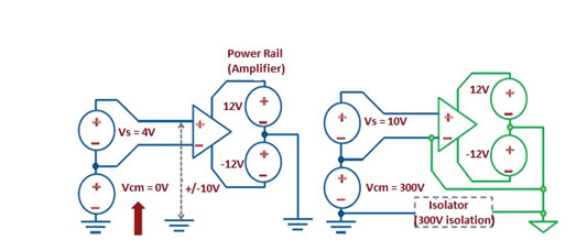
รูปด้านบนแสดงให้เห็นระบบวัดสองระบบ ระบบด้านขวามีไอโซเลชั่นในตัว
Figure above shows two measurement systems, the right one used with the inbuilt isolation.
เนื่องจากระบบแรกไม่มีไอโซเลชั่นระหว่างกราวนด์ของแหล่งจ่ายแรงดันไฟฟ้า กราวนด์ของระบบและกราวนด์ของอุปกรณ์ ซึ่งอาจทำให้เกิดกระแสไฟฟ้าไหลในกราวนด์ลูปของระบบวัดซึ่งมีผลกับความแม่นยำของค่าที่วัดได้
Because in the first system, the source ground, system ground and equipment ground are non-isolated and are at different potentials, this causes a ground loop current to flow within the measurement system and thereby affecting the accuracy of measured voltage.
ในระบบวัดที่มีไอโซเลชั่น กราวนด์ลูปจะไม่สามารถเกิดขึ้นได้เนื่องจากกราวนด์ของแหล่งจ่ายแรงดันไฟฟ้า กราวนด์ของระบบและกราวนด์ของอุปกรณ์ถูกแยกออกจากกัน ซึ่งทำให้ระบบวัดแบบนี้มีความแม่นยำมากขึ้น
In the measurement system with isolation, the formation of ground loop is prevented by isolating Equipment ground from System ground and Source ground and thus the measurement system with isolation provide more accurate readings.
เราลองมาทำความเข้าใจว่าเกี่ยวกับแรงดันไฟฟ้าร่วมและไอโซเลชั่นจะช่วยปรับปรุงในเรื่องนี้ได้อย่างไร?
Using the same diagram, let us understand Common mode voltage and how isolation is needed to improve the common mode voltage range.
แรงดันไฟฟ้าร่วม คือ ช่วงแรงดันไฟฟ้าที่สามารถเปลี่ยนแปลงได้เมื่อเทียบกับกราวนด์ของระบบวัด ในระบบวัดแบบดิฟเฟอเรนเชี่ยล (differential) ที่ไม่มีไอโซเลชั่นซึ่งมีการเชื่อมต่อทางไฟฟ้าระหว่างอินพุทและเอาท์พุท ดังนั้นคุณสมบัติทางไฟฟ้าของวงจรขยายจะเป็นตัวกำหนดค่าแรงดันไฟฟ้าร่วมของอินพุท แต่ถ้าเราใช้วงจรขยายแบบที่มีไอโซเลชั่นซึ่งไม่มีการเชื่อมต่อทางไฟฟ้าระหว่างอินพุทและเอาท์พุท คุณสมบัติทางด้านแรงดันไฟฟ้าร่วมจะดีขึ้นเป็นอย่างมาก
The common-mode voltage range is defined as the maximum allowable voltage swing on each input with respect to the measurement system ground. In a non-isolated differential measurement system, an electrical path still exists in the circuit between input and output. Therefore, the electrical characteristics of the amplifier limit the common-mode signal level that you can apply to the input. With the use of isolation amplifiers, the conductive electrical path is eliminated and the common-mode rejection ratio is dramatically increased.
สำหรับวงจรทางด้านซ้ายซึ่งไม่มีไอโซเลชั่นระหว่างอินพุทและเอาท์พุทซึ่งเป็นเรื่องปกติในระบบวัดทั่ว ๆ ไป แรงดันไฟฟ้าร่วมต้องมีค่าเป็น 0 โวลท์เพื่อให้อินพุทสามารถป้อนได้ระหว่าง -10 ถึง 10 โวลท์ในขณะที่วงจรทางด้านขวาซึ่งมีไอโซเลชั่นระหว่างอินพุทและเอาท์พุทของวงจรขยายสามารถป้อนอินพุทและเอาท์พุทได้ระหว่าง -10 ถึง 10 โวลท์แม้จะมีแรงดันไฟฟ้าร่วมสูงถึง 300 โวลท์โดยไม่มีผลกับความแม่นยำและยังมีความปลอดภัยในการวัดอีกด้วย
For the circuit on the left, there is no isolation between the inputs and output of the amplifier which is typically a component in the measurement system. Because of zero isolation, the common mode voltage, Vcm is 0V and thus the source voltage Vs needs to be within +/-10V, whereas in the circuit on the right, sufficient isolation is provided between the inputs and output of the amplifier which ensures that even though Vcm is 300V, the source Voltage, Vs which is in +/- 10V range of Vcm can be measured accurately and with no safety compromise.
การออกแบบไอโซเลชั่น
Design for Isolation
การใช้งานในรูปแบบที่แตกต่างกันย่อมต้องการไอโซเลชั่นที่แตกต่างกัน ซึ่งไอโซเลชั่นในเครื่องมือวัดนั้นมีหลากลหลายรูปแบบ
Different applications need different types of isolation and there are multiple ways of implementing isolation in measurement devices.
ไอโซเลชั้น 3 แบบจะถูกกล่าวถึงในที่นี้โดยเริ่มจากแบบพื้นฐาน (ความปลอดภัยต่ำ) ไปจนถึงแบบที่สมบูรณ์แบบ (ความปลอดภัยสูง)
a. ไอโซเลชั่นระหว่างช่องสัญญาณกับเอิร์ธ (Channel to Earth Ground)
b. ไอโซเลชั่นระหว่างกลุ่มของช่องสัญญาณ (Bank to Bank)
c. ไอโซเลชั่นระหว่างช่องสัญญาณ (Channel to Channel isolation)
ลองมาทำความเข้าใจไอโซเลชั่นแบบต่าง ๆ กันดู
The 3 types of isolation techniques can be listed from basic (low level protection) to complete (high level protection) in the order of
d. Channel to Earth Ground
e. Bank to Bank
f. Channel to Channel isolation
Let’s now understand the different isolation techniques.
1. ไอโซเลชั่นระหว่างช่องสัญญาณกับเอิร์ธ (Channel to Earth Ground)
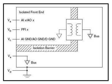
ไอโซเลชั่นแบบนี้ช่องสัญญาณกับเอิร์ธจะแยกจากกันทางไฟฟ้าดังแสดงในรูปด้านล่าง แรงดันไฟฟ้าด้านที่ป้อนสัญญาณเข้ามาจะไม่มีการไอโซเลชั่นระหว่างช่องสัญญาณแต่จะมีการแยกจากกันทางไฟฟ้าระหว่างช่องสัญญาณกับเอิร์ธ นี่เป็นไอโซเลชั่นขั้นพื้นฐานที่สุดและถ้าอุปกรณ์มีการไอโซเลชั่นระหว่างกลุ่มของช่องสัญญาณหรือระหว่างช่องสัญญาณก็จะมีการไอโซเลชั่นแบบนี้ด้วย
Note: การแรเงาในภาพด้านล่างแสดงให้เห็นถึงบริเวณที่มีการไอโซเลชั่นซึ่งทำให้เกิดการแยกจากกันทางไฟฟ้าขึ้น สัญลักษณ์หม้อแปลงแสดงให้เห็นถึงการแยกจากกันทางไฟฟ้าเชิงกลเพื่อใช้ในการส่งสัญญาณข้ามไอโซเลชั่นโดยสร้างสนามแม่เหล็กไฟฟ้าที่แปรผันตามสัญญาณไฟฟ้า
1. Channel-to-Earth Ground Isolation
Channels of the device and the device's Earth ground are electrically isolated from one another. Channel-to-Earth isolation is represented in the Figure below. Voltages of the isolated front end (Va-c ) are on the same bus; these voltages are not isolated from one another. Ve,d are on a separate bus and are isolated from the front end. This is the most fundamental type of isolation and this protection is covered by bank and channel-to-channel isolation.
Note: For the following diagrams, the diagonal hash marks indicate the isolation barrier, this separates circuitry. The transformer symbols represent electromagnetic isolation used to couple a signal across the isolation barrier by generating an electromagnetic field proportional to the electrical signal.
2. ไอโซเลชั่นระหว่างกลุ่มของช่องสัญญาณ (Bank to Bank)
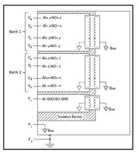
ไอโซเลชั่นแบบนี้ช่องสัญญาณของเครื่องมือวัดจะถูกจัดเป็นกลุ่มเพื่อใช้งานวงจรขยายแบบที่มีไอโซเลชั่นร่วมกันดังแสดงในภาพด้านล่าง ในการไอโซเลชั่นแบบนี้จะมีข้อจำกัดในเรื่องแรงดันไฟฟ้าร่วมระหว่างช่องสัญญาณที่อยู่ในกลุ่มเดียวกัน แต่ช่องสัญญาณที่อยู่คนละกลุ่มจะไม่มีปัญหาเรื่องนี้ กล่าวคือ ไม่มีการแยกจากกันทางไฟฟ้าระหว่างช่องสัญญาณแต่จะมีการแยกจากกันทางไฟฟ้าระหว่างกลุ่มของช่องสัญญาณและเอิร์ธนั่นเอง ไอโซเลชั่นแบบนี้มีใช้ทั่วไปในระบบวัดสัญญาณดิจิตอล
2. Bank (Channel-to-Bus) Isolation
Channels of a device are banked (grouped) together to share a single isolation amplifier. Figure below represents Bank isolation. In this topology, the common-mode voltage difference between channels is limited, but the common-mode voltage between the bank of channels and the non-isolated part of the measurement system can be large. In other words, individual channels are not isolated, but the channel groups are isolated from one another and earth ground. Bank1, Bank2, Vi, and Vj,k are on separate buses and isolated from one another. Bank isolation is most commonly used in Digital I/O measurement systems.
3. ไอโซเลชั่นระหว่างช่องสัญญาณ (Channel to Channel isolation)
ไอโซเลชั่นแบบนี้แต่ละช่องสัญญาณและชิ้นส่วนที่ไม่มีไอโซเลชั่นจะถูกแยกจากกันทางไฟฟ้าดังแสดงในภาพด้านล่าง หม้อแปลงในภาพเป็นอุปกรณ์ที่ใช้ในการสร้างไอโซเลชั่นซึ่งสามารถทดแทนด้วยออปโตคัปเปลอร์หรือไอซีแบบดิจิตอล
3. Channel-to-Channel Isolation
Each channel is isolated from every other channel and other non-isolated components. Figure below represents channel-to-channel isolation. Va,b, Vc,d, Ve,f, and Vg,h are all on separate buses and are isolated from one another.
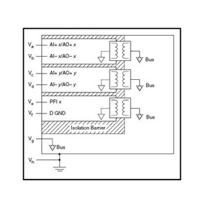
In the figures above, the transformer represents the isolator implementation, could also be replaced by an Opto-coupler or a Digital IC.
ทำความเข้าใจข้อกำหนดทางเทคนิคของไอโซเลชั่น เช่นเดียวกับแบนวิธและความถี่ในการสุ่มสัญญาณ ไอโซเลชั่นสำหรับเครื่องมือวัดก็มีข้อกำหนดทางเทคนิค ซึ่งการเลือกเครื่องมือวัดให้ถูกต้องก็จำเป็นต้องเข้าใจข้อกำหนดทางเทคนิคเหล่านี้
Understanding Isolation Specifications
Just like bandwidth, sampling rate etc Isolation is also specified for the Measurement System and to choose a right system for the application it is important to understand the specifications related to Isolation.
1.แรงดันไฟฟ้าร่วม
แรงดันไฟฟ้าร่วม คือ ค่าความต่างศักย์ระหว่างจุดอ้างอิงของระบบวัดกับกราวนด์ของเอิร์ธ ถ้าข้อระบุทางเทคนิคกำหนดว่า ความต่างศักย์ระหว่างจุดอ้างอิงและเอิร์ธกราวนด์ไม่เกิน +/-300 โวลท์และระหว่างช่องสัญญาณไม่เกิน +/-10 โวลท์ เราสามารถวัดสัญญาณ +/-10 โวลท์เมื่อเทียบกับจุดอ้างอิงได้โดยที่ค่าความต่างศักย์เมื่อเทียบกับกราวนด์ไม่เกิน +/-300 โวลท์
1. Common Mode Voltage
Common mode voltage is spec’ed as COM to Earth Ground which basically is the potential difference between the COM of the measurement system and the Earth Ground.
Let’s say COM to Earth Ground is spec’ed at +/-300V and Channel to COM, Channel to Channel is spec’ed at +/-10V. This Measurement System can successfully measure a signal of +/-10V with reference to COM and since the maximum isolation of COM with respect to Earth Ground is +/-300V, one can measure signals of +/-10V with reference to +/-300V using this Measurement System.
2.แรงดันไฟฟ้าต่อเนื่อง
ค่า RMS สูงสุดทั้งของไฟฟ้ากระแสสลับและไฟฟ้ากระแสตรงที่ไอโซเลชั่นสามารถทนได้
2. Continuous Voltage
The highest possible root-mean-square value of the ac and dc voltage across insulation.
3.แรงดันไฟฟ้าที่สามารถทนได้
แรงดันไฟฟ้าที่เกิดจากไฟกระชากที่อุปกรณ์สามารถทนได้ในระยะเวลาสั้น ๆ โดยไม่มีความเสียหายเกิดขึ้นกับระบบวัด มักจะถูกระบุในรูปแบบ x โวลท์เป็นเวลา t วินาที
3. Withstand Voltage
The transient voltage the device can withstand for a brief period of time without damaging the measurement system. Withstand Voltage is specified like X Volts for t seconds.
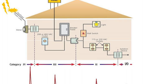
4.รูปแบบการติดตั้ง
รูปแบบการติดตั้งนั้นขึ้นอยู่กับแรงดันไฟฟ้าที่เกิดจากไฟกระชากซึ่งคาดว่าจะเกิดขึ้น ระบบวัดส่วนใหญ่จะใช้แบบ CAT I และ CAT II
4. Installation Category
Depending upon the expected magnitude of transients, Isolation category of the measurement system is chosen. Most of the measurement systems fall in Category I and Category II.
5.มาตรฐานด้านความปลอดภัย
มาตรฐานด้านความปลอดภัยของเครื่องมือวัดมีหลากหลายรูปแบบ แบบที่แพร่หลายที่สุด คือ IEC 61010-01 ซึ่งมีการใช้งานกันทั่วโลก มาตรฐานอื่น ๆ ซึ่งมีการใช้งานในระดับภูมิภาคถูกแสดงไว้ด้านล่าง
1. อเมริกาเหนือ UL 61010 -01
2. แคนาดา CAS 61010-01
3. ยุโรป EN 61010-01
5. Safety Standard
There are multiple safety standards specified for measurement systems. The most common is IEC 61010-01 which is followed globally. Some geo-specific standards are also followed, listed below
4. N. America UL 61010 -01
5. Canada CAS 61010-01
6. Europe EN 61010-01
เราต้องการไอโซเลชั่นแบบไหน?
ที่ผ่านมาเราพูดคุยเกี่ยวกับไอโซเลชั่นแบบต่าง ๆ และข้อกำหนดทางเทคนิคที่เกี่ยวข้อง แต่เราจะทราบได้อย่างไรว่าเราต้องใช้ไอโซเลชั่นแบบไหนในระบบวัดของเรา?
แผนผังด้านล่างช่วยให้เราสามารถเลือกไอโซเลชั่นได้ถูกต้องตามความต้องการ
Which Isolation do I need?
So far, we have discussed different types of isolation and the associated specifications but how does one as a user choose the right isolation in the measurement system?
The flowchart below will help select the right type of isolation.
เราสามารถเลือกระบบวัดที่ถูกต้องได้ขึ้นอยู่กับชนิดของไอโซเลชั่นที่ต้องการใช้งาน ซึ่งไอโซเลชั่นแต่ละแบบก็มีค่าใช้จ่ายที่แตกต่างกันไป ซึ่งแน่นอนว่าไอโซเลชั่นระหว่างช่องสัญญาณนั้นมีค่าใช้จ่ายสูงสุดทว่ามีความปลอดภัยสูงสุด
Depending on the type of isolation one needs for the industrial application, the right measurement system can be selected. There is a tradeoff between the type of isolation and the cost associated with it. As expected, the channel to channel isolation is the costliest and the safest.
เนชั่นแนลอินสทรูเม้นส์ ผู้นำด้านระบบวัดซึ่งมีทั้งซอฟท์แวร์ออกแบบระบบวัดด้วยกราฟฟิคและเครื่องมือวัดแบบโมดูล่าร์ในรูปแบบ PXI USB และ Ethernet ซึ่งช่วยให้มีค่าใช้จ่ายที่เหมาะสมกับสิ่งที่จะได้รับ
National Instruments, a pioneer in Data Acquisition (DAQ) systems provides Graphical Software and Modular DAQ cards in PXI, USB and Ethernet form factor which offers the right cost Vs benefit portfolio.
ยกตัวอย่างเช่น PXIe SC Express ซึ่งมีไอโซเลชั่นระหว่างกลุ่มช่องสัญญาณสำหรับการวัดด้วยเทอร์โมคัปเปิ้ลและอาร์ทีดี และไอโซเลชั่นระหว่างช่องสัญญาณสำหรับแรงดันไฟฟ้าทั้งอินพุทและเอาท์พุท NI 9244 ซึ่งสามารถวัดแรงดันไฟฟ้าระหว่างสายสัญญาณได้สูงถึง 800 โวลท์และมีไอโซเลชั่นระหว่างช่องสัญญาณแบบ CAT-III สูงถึง 400 โวลท์ อินพุทและเอาท์พุทแบบดิจิตอลและเคาน์เตอร์ของเนชั่นแนลอินสทรูเม้นส์เกือบทั้งหมดมีไอโซเลชั่นระหว่างกลุ่มของช่องสัญญาณเพื่อที่ผู้ใช้งานจะสามารถสร้างระบบวัดที่มีความทนทานและความปลอดภัย นอกจากนี้โมดูล C series ทุกรุ่นของเนชั่นแนลอินสทรูเม้นส์มีไอโซเลชั่นระหว่างช่องสัญญาณกับเอิร์ธ
For instance, the NI PXIe SC Express series provides bank isolation for Thermocouple and RTD measurements and Channel –Channel isolation for Voltage input and output. The NI C Series NI 9244 which can measure 800Vrms Line-Line provides 400Vrms Cat -III Channel-Channel Isolation. Almost all the NI Digital I/O and Counter I/O cards have bank isolation so that the users can build robust and safe measurement systems for their applications. All the NI C series cards have Channel to Earth Ground isolation which is the bare minimum isolation.
สงวนลิขสิทธิ์ ตามพระราชบัญญัติลิขสิทธิ์ พ.ศ. 2539 www.thailandindustry.com
Copyright (C) 2009 www.thailandindustry.com All rights reserved.
ขอสงวนสิทธิ์ ข้อมูล เนื้อหา บทความ และรูปภาพ (ในส่วนที่ทำขึ้นเอง) ทั้งหมดที่ปรากฎอยู่ในเว็บไซต์ www.thailandindustry.com ห้ามมิให้บุคคลใด คัดลอก หรือ ทำสำเนา หรือ ดัดแปลง ข้อความหรือบทความใดๆ ของเว็บไซต์ หากผู้ใดละเมิด ไม่ว่าการลอกเลียน หรือนำส่วนหนึ่งส่วนใดของบทความนี้ไปใช้ ดัดแปลง โดยไม่ได้รับอนุญาตเป็นลายลักษณ์อักษร จะถูกดำเนินคดี ตามที่กฏหมายบัญญัติไว้สูงสุด